ECE 4160 Fast Robots
Raphael Fortuna
Lab reports made by Raphael Fortuna @ rafCodes Hosted on GitHub Pages — Theme by mattgraham
Home
Lab 5: Motors and Open Loop Control
Summary
In this lab I soldered wires to the motor drivers and connected them to the Artemis. I ran PWM tests on the motor drivers and checked it with an oscilloscope to make sure it was working. Next the car was modified to use the motor drivers and tested to make sure everything was installed correctly. Finally, open loop control was added and tested.
Prelab
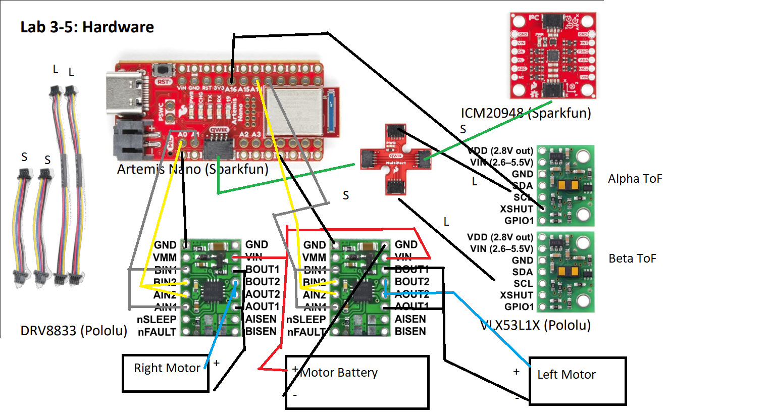
I read the documentation and datasheet for the dual motor driver and found that VIN was 2.7-10.8 volts, ground was common for each side, and AIN1, 2 and BIN1, 2 were for the PWM input signals. I also found that AOUT1, 2 and BOUT1, 2 are for the DC motors and will be wired together according to number – 1 with 1, 2 with 2 – for both the IN and OUT connections.
Each channel can supply 1.2 A per second, with a peak of 2A for a few seconds, which is why the OUTs will be wired together in parallel as described by the manual to give 2.4 A per second with a peak of 4A.
The GPIO pins I will be using are GPIO 16,15, 2, and 3 since each pin only has 1-2 extra functions, reducing the lost functionality on the Artemis. 16 and 15 are next to each other as are 2 and 3, but the pairs are far from each other, making it easier to solder them and keep track of the pins.
The Artemis and motors/motor drivers are being powered by different batteries to reduce EMI noise coming from the motors.
I have soldered jumper wires that I cut to the Artemis and motor drivers to make it easier to repair them since they can be unplugged and used flex-core wire on the wires coming from the motor driver to avoid breakages.
Soldering the Motor Driver Task
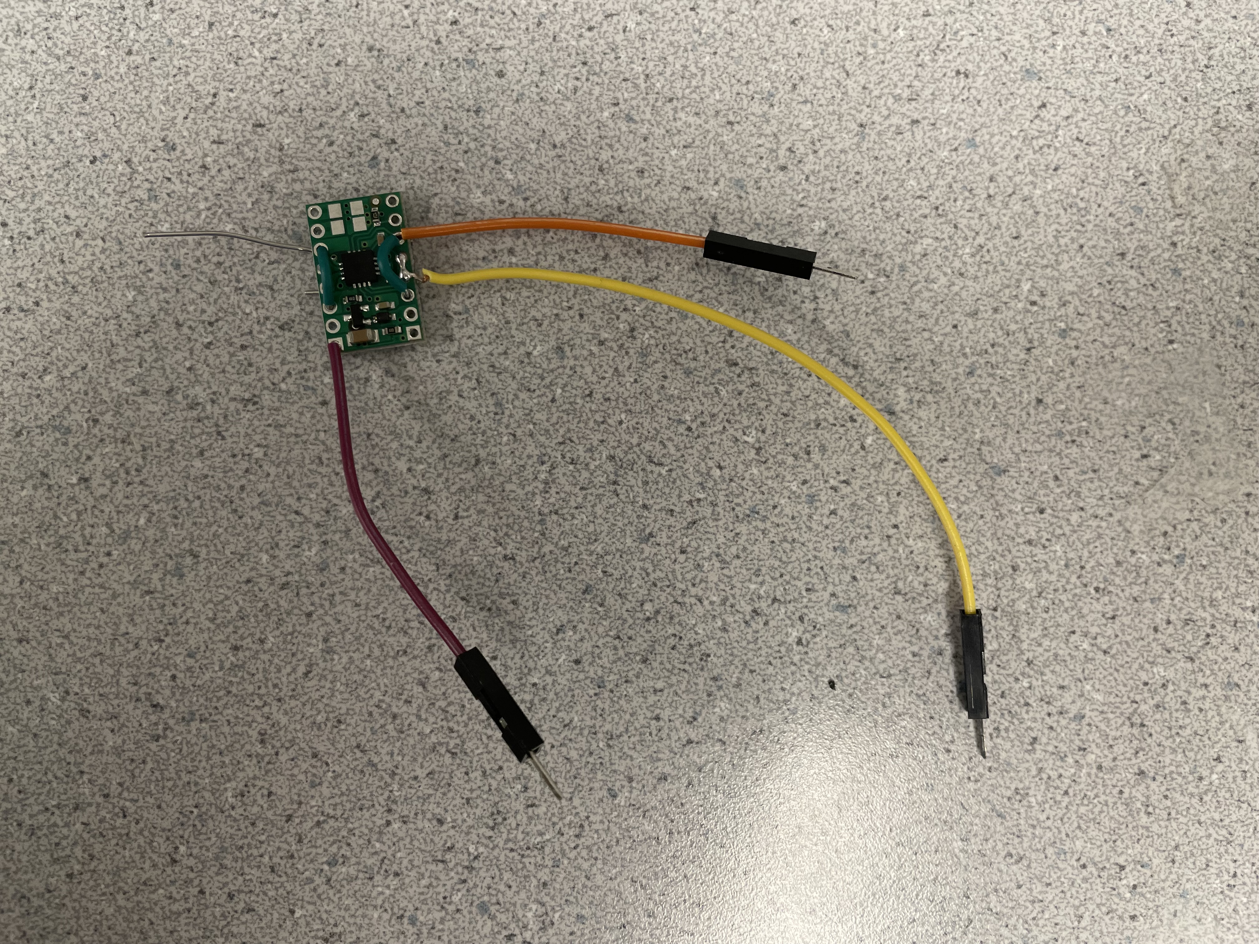
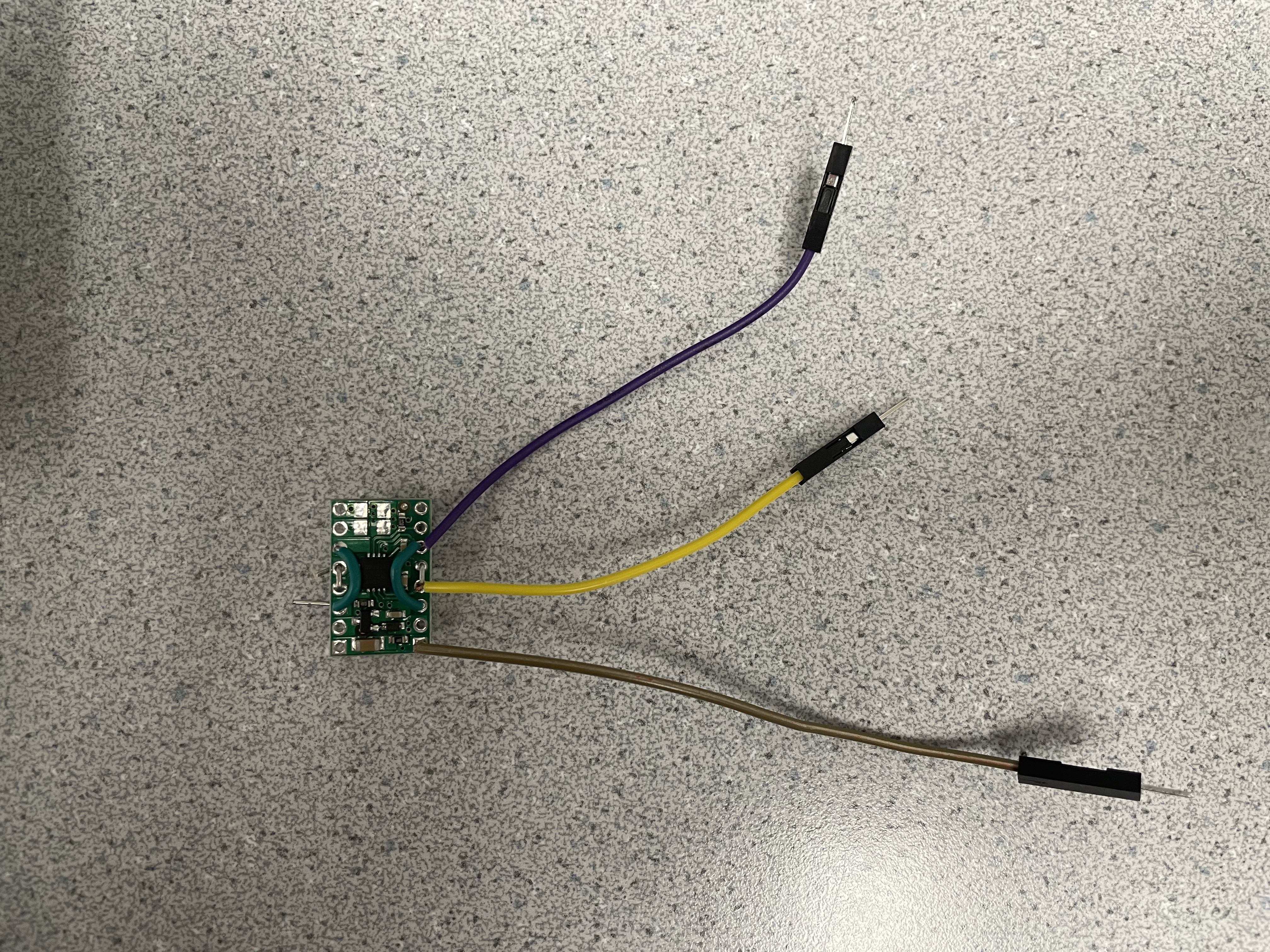
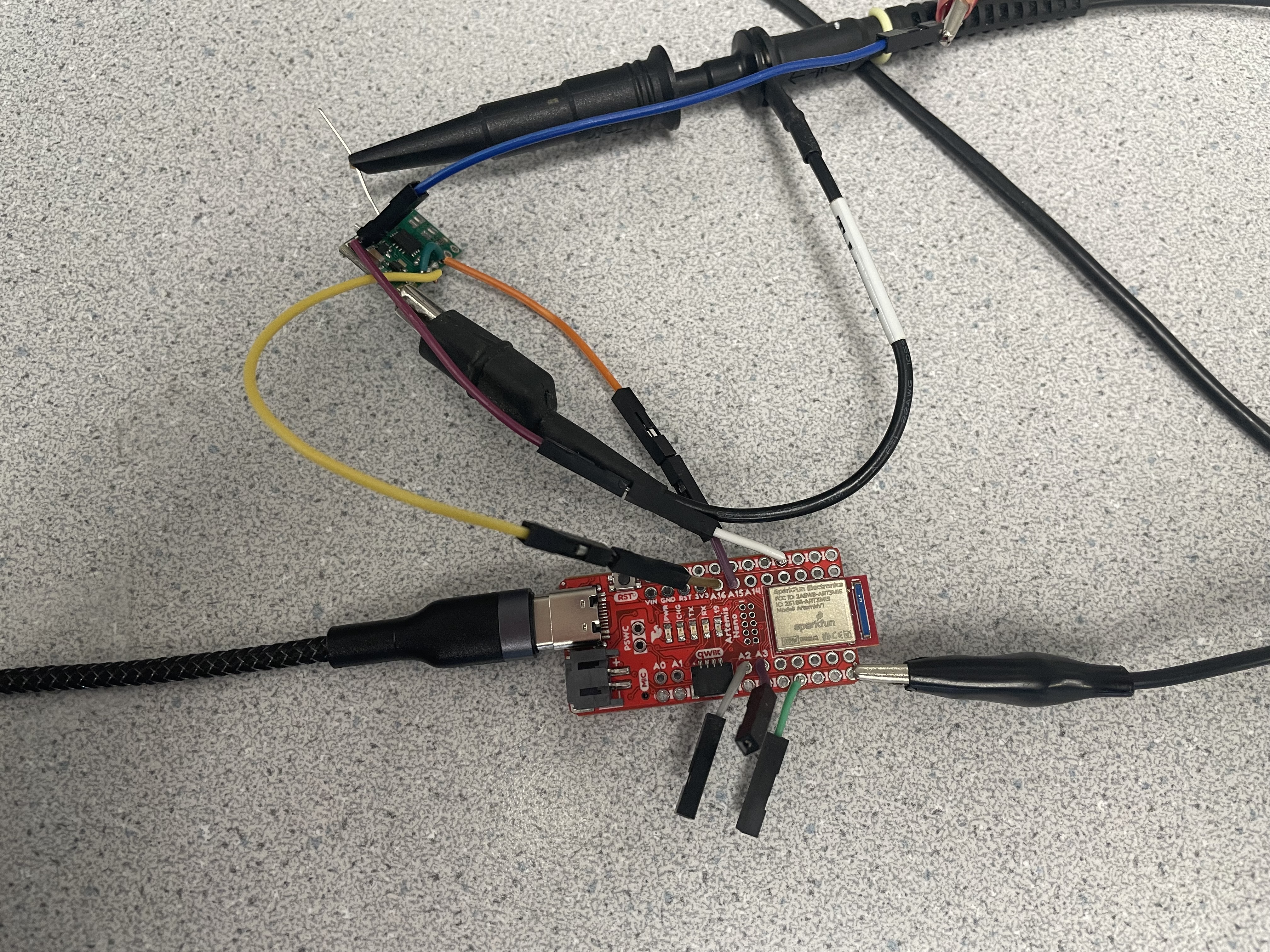
I soldered wires with jumper headers on them to the motor drivers and Artemis to make fixing and testing them easier and reducing their shape profile. I used small solid-core wires for the connections for the IN and OUT pins on the motor controller since they will not be moving and are next to each other. A picture of the soldered motor driver and Artemis is below.
I will use 3.7 V and 1.5 A for the power supply since this is below the maximum peak of the motor driver and the battery outputs 3.7 V from its pins.
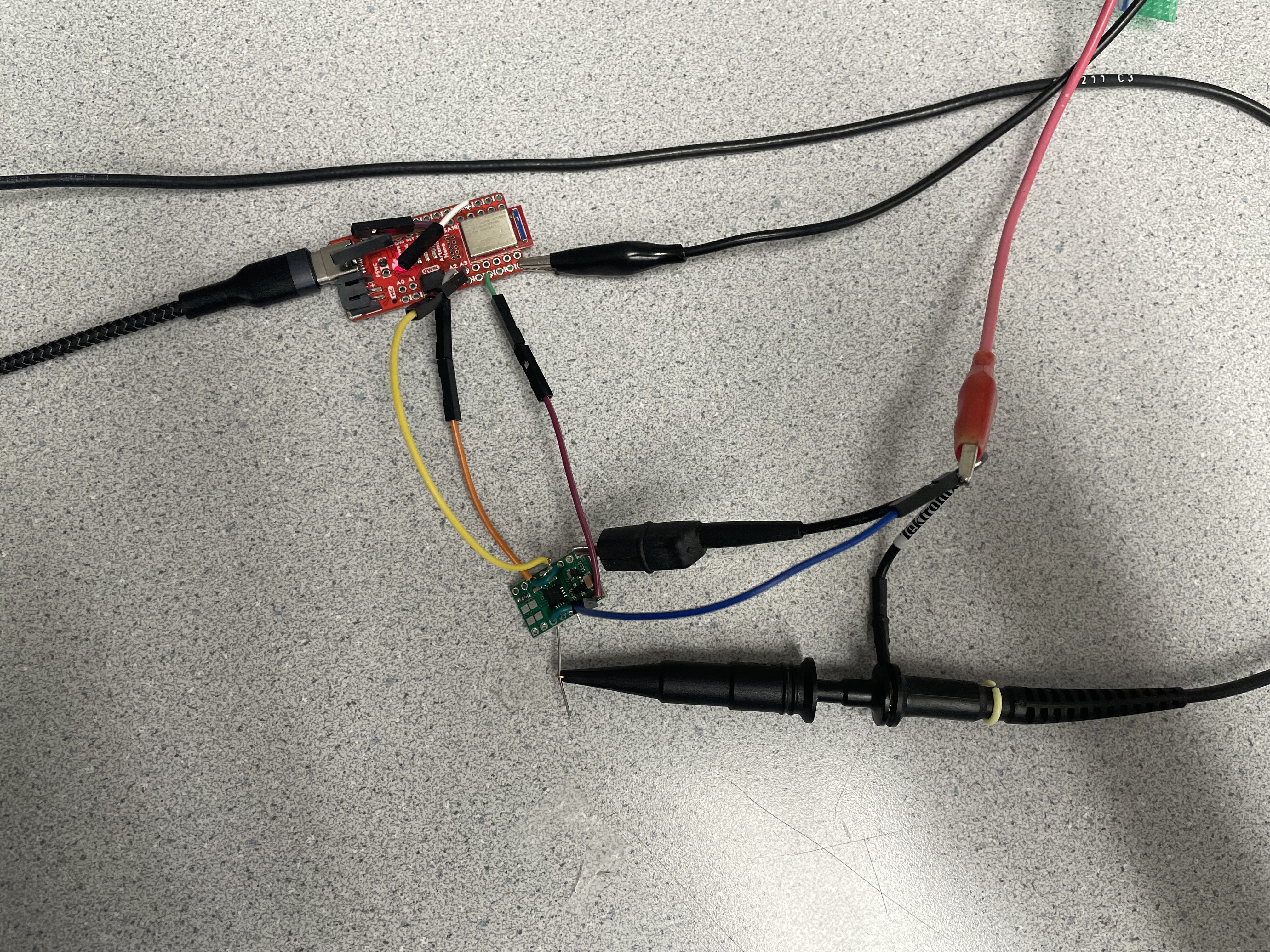
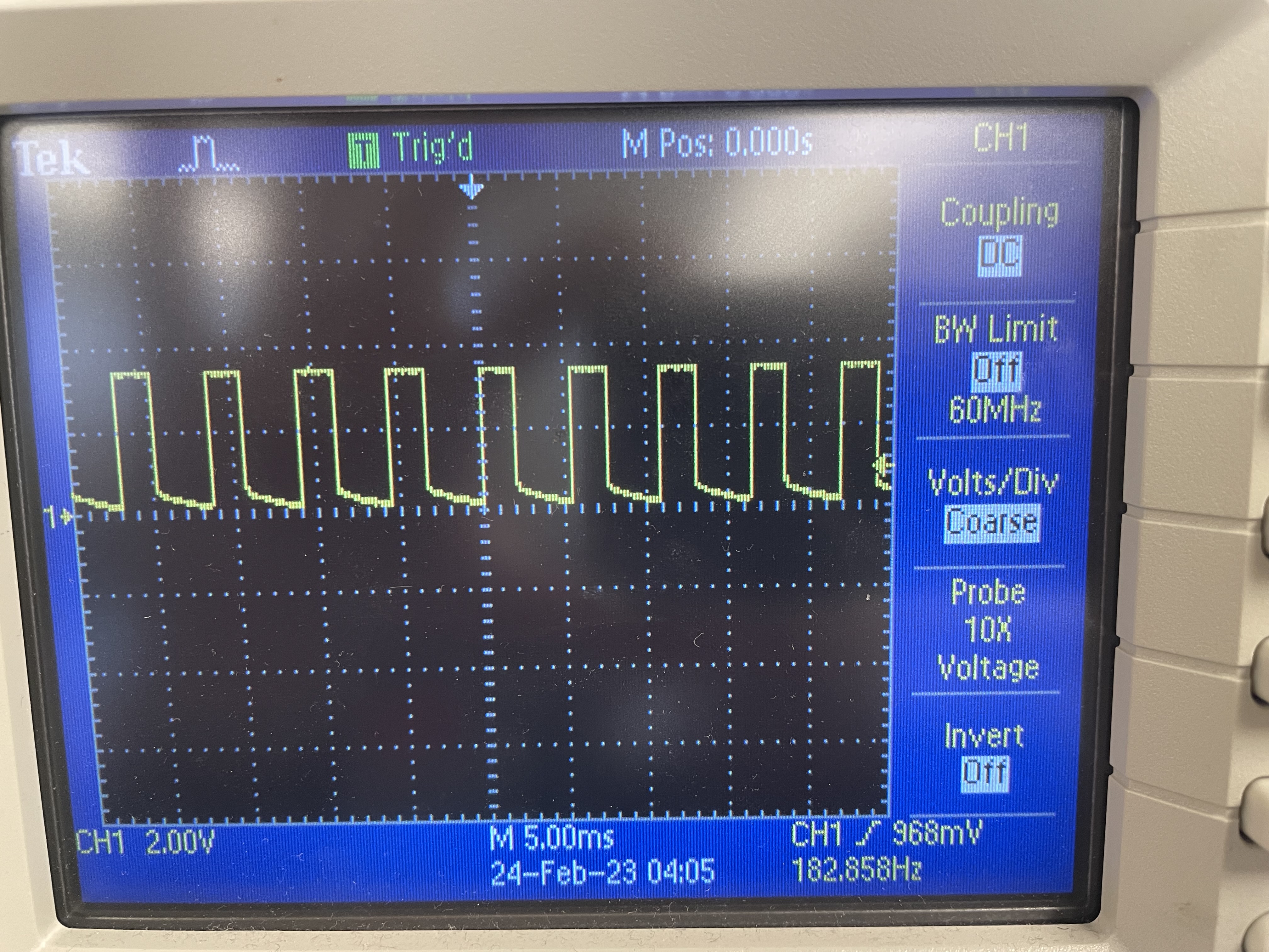
Here is the code I used to test the motor drivers with the PWM signal of 100 and then 50:
Car Disassembly Task
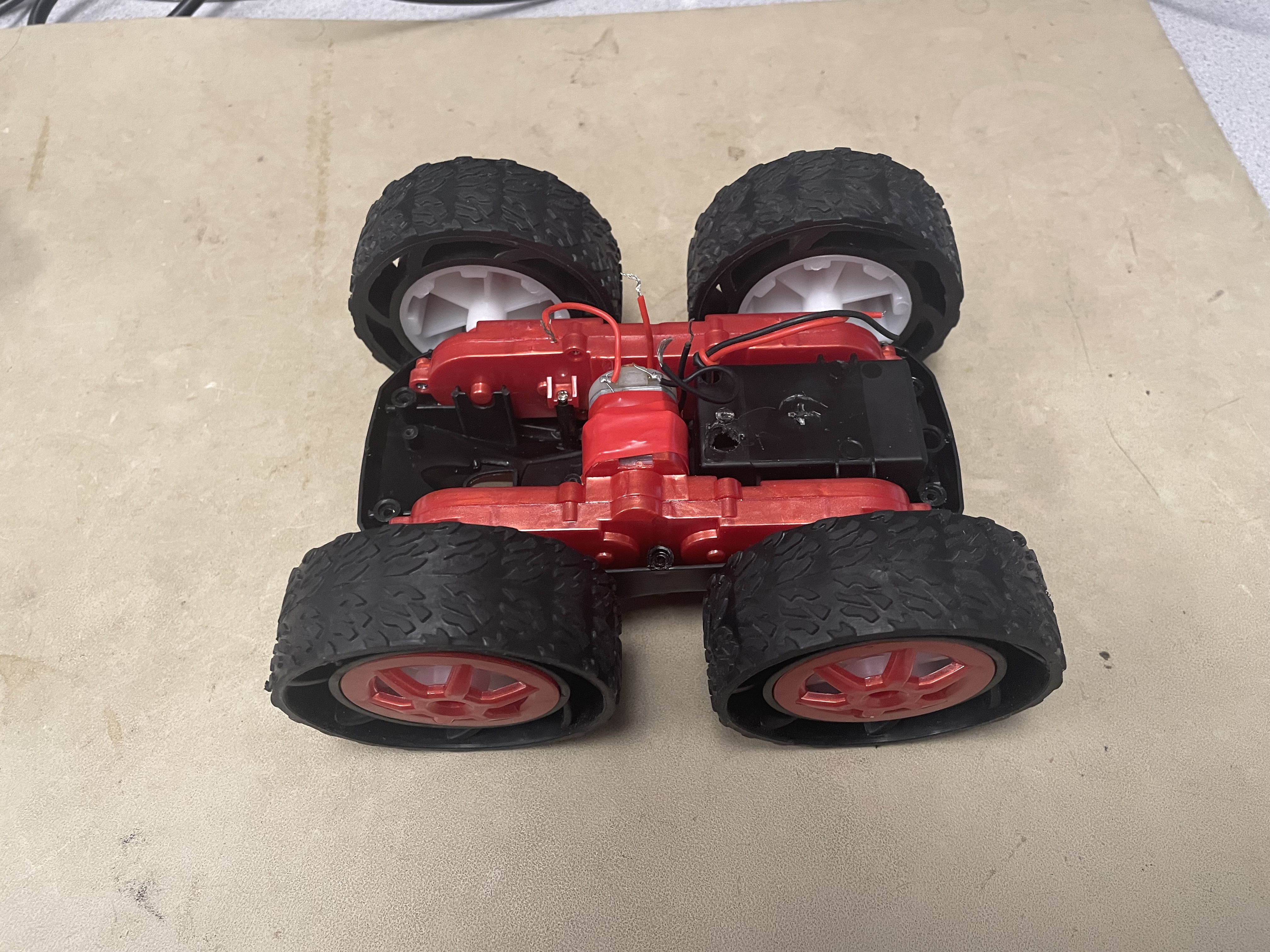
I disassembled the car next. I first removed the top, removed the LEDs, removed the bottom LED covers, cut the motor and power wires to remove the circuit board, and poked a hole into the battery holder compartment to pass the Artemis battery wire through.
Motor Driver Test Task
I connected the motor driver to the car motor and was able to run the motor in both directions as seen below with the Artemis using PINS 16 and 15. I made sure to connect all ground together.
Motor Driver Battery Test Task
I soldered the battery connector to the motor driver and was able to use it to power the motor driver and move the car wheels as seen below.
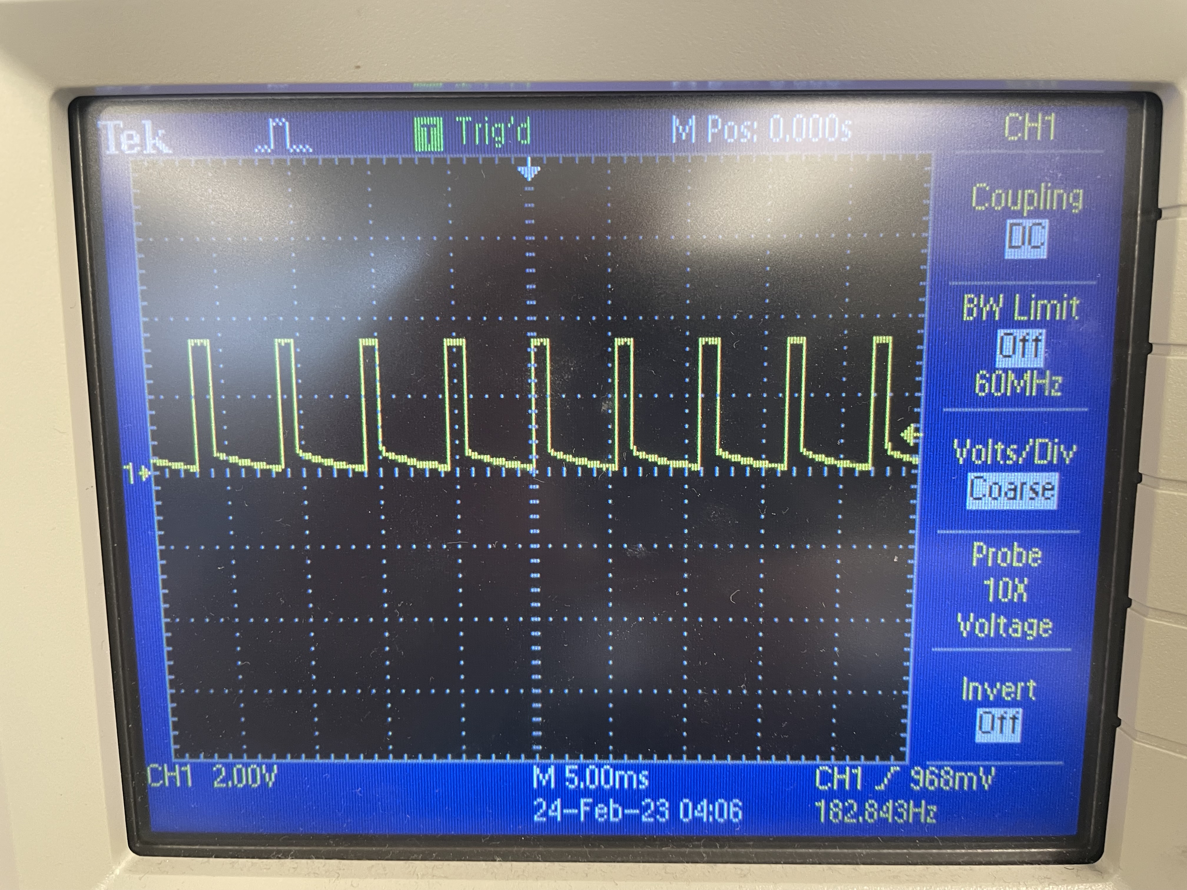
I then repeated the above tasks for the second motor driver and used the 2, 3 pins instead of the 16, 15 pins. Below is the oscilloscope wave form and the two motor driving tests.
Here are two photos of the waveforms for 100 PWM and 25 PWM signals respectively
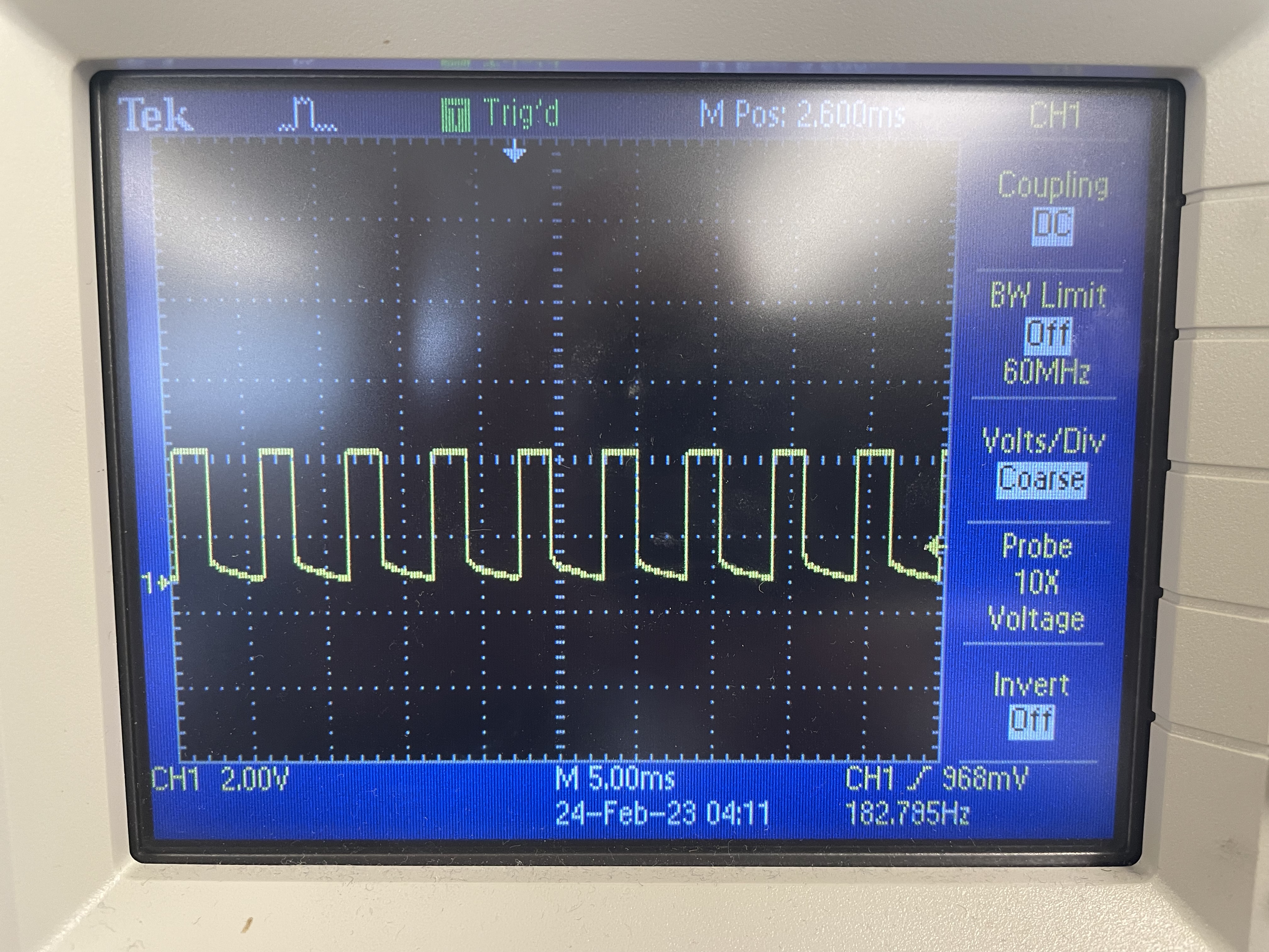
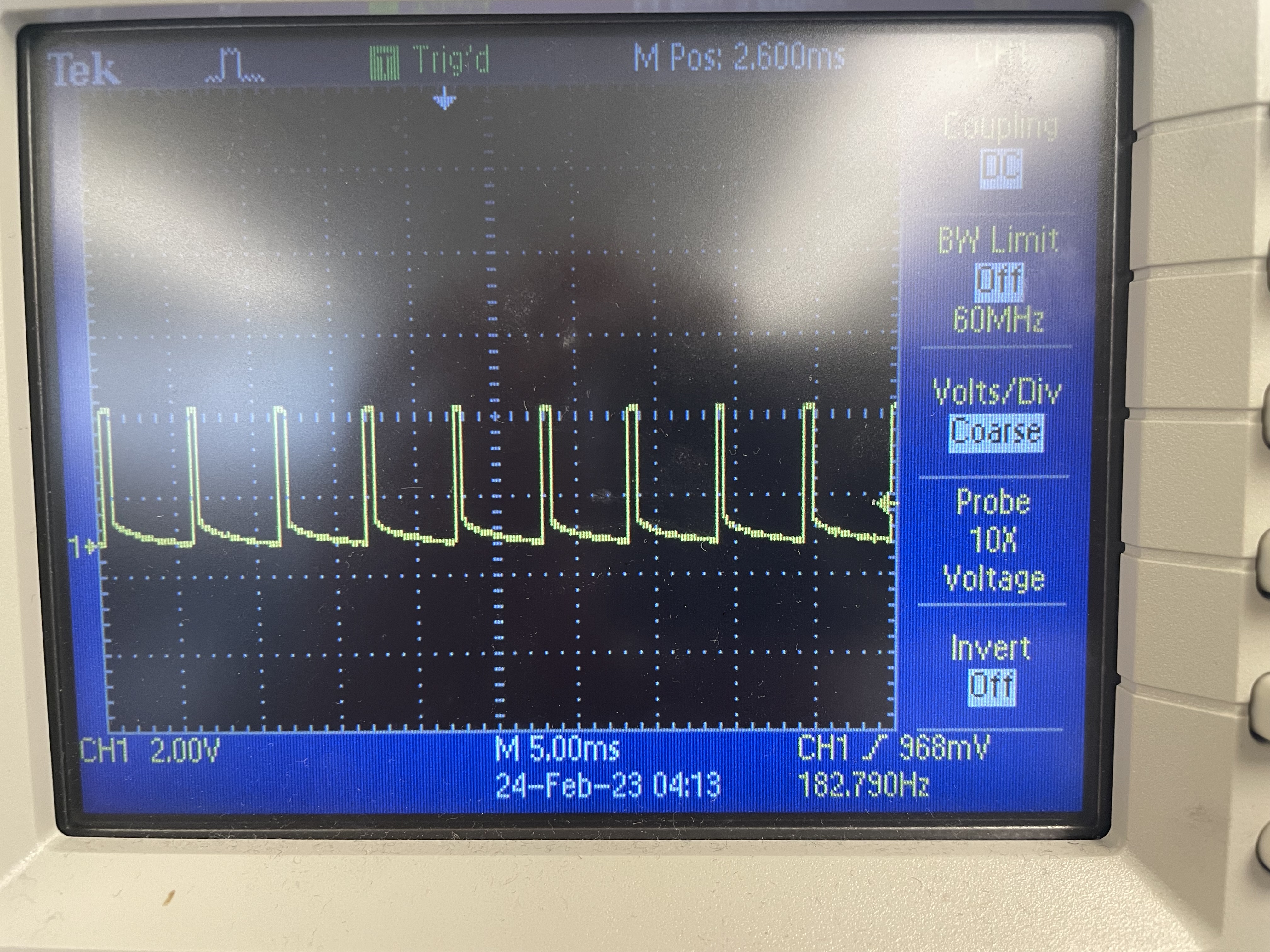
I connected both the motor controllers to the Artemis with their appropriate pins and grounds and was able to make both sides of the car’s wheels spin as seen below.
Part Installation Task
The next step was to install the Artemis, motor drivers, ToF, IMU, and batteries into the car. I made sure to twist the wires to reduce EMI effects.
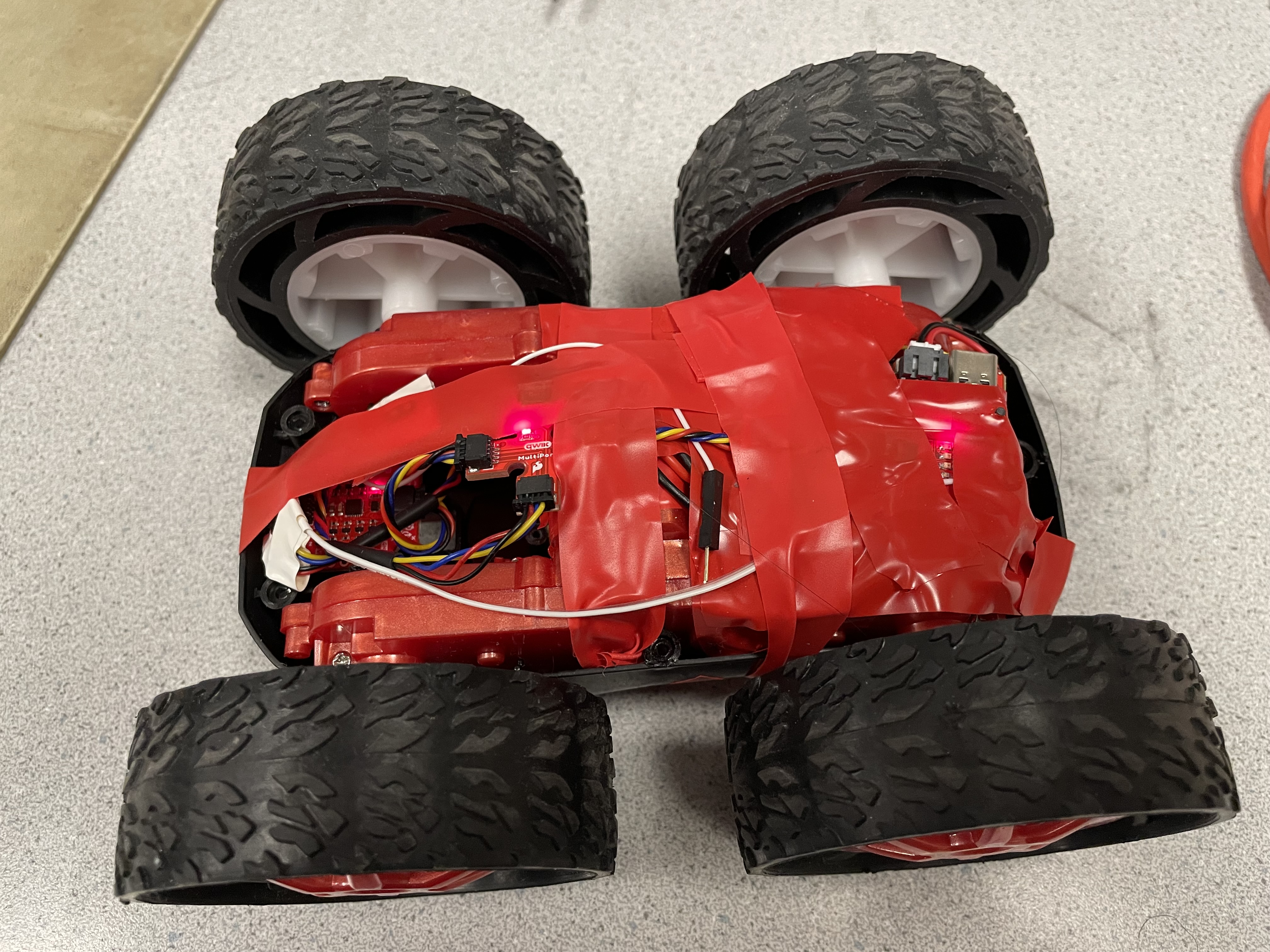
I drove the car around and added a timer for the car to stop after a few seconds this can be seen in the Open Loop Control Task video.
PWM Task
I modified the code above to find what the smallest PWM value was that would still move the car. I found that the PWM values were:
Left side of robot: 60
Right side of robot: 60
The car was unable to use the left motor to turn on its axis even at max power, without a little push, the left motor was unable to move.
Calibration Task
At nearly max power with the left motor – 230 PWM vs 70 PWM for the right motor – it was able to go somewhat go straight. This imbalance is strange and the left motor is unable to turn itself even at max power on the ground.
At nearly max power with the left motor – 230 PWM vs 70 PWM for the right motor – it was able to go somewhat go straight. This imbalance is strange and the left motor is unable to turn itself even at max power on the ground.
Open Loop Control Task
Although the car was having issues with calibration, I added functions for the car to turn right and left. I did this by reversing the directions of one of the sides of the car – left side for turning right, right side for turning left – and letting it move for a certain amount of time. I also added a function for it to drive forward. I also added keyboard functionality for tuning the PWM that I used above as well as for driving the car from Python as seen below.